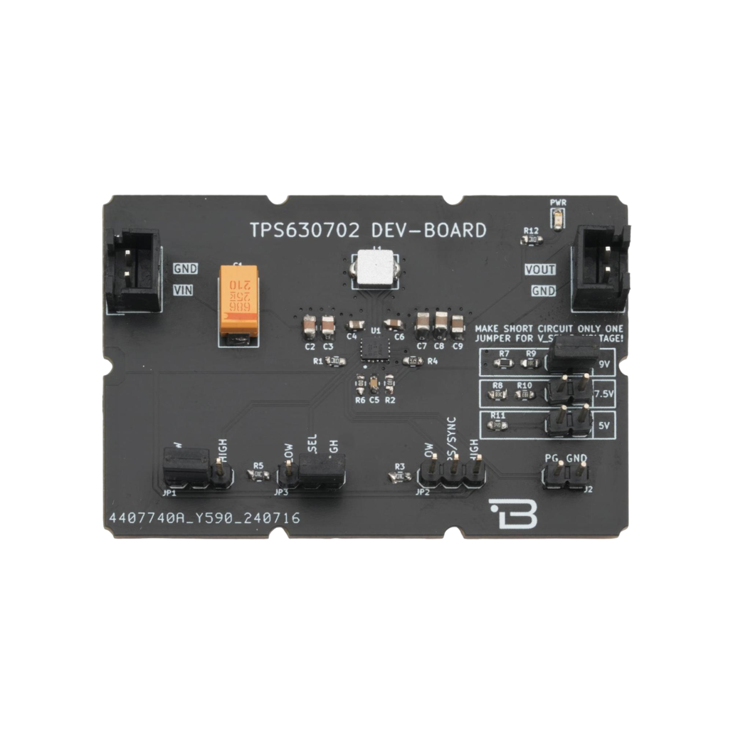
TPS630702RNMT Breakout Board

SKU:

The TPS630702 is a high efficiency, low quiescent current buck-boost converter suitable for applications where the input voltage can be higher or lower than the output voltage

Output currents can go as high as 2A in boost mode and in buck mode. The buck-boost converter is based on a fixed frequency, pulse-width modulation (PWM) controller using synchronous rectification to obtain maximum efficiency. At low load currents, the converter enters Power Save Mode to maintain high efficiency over a wide load current range. The converter can be disabled to minimize battery drain. During shutdown, the load is disconnected from the battery

Recommended Price:

Key Features

  • Input Voltage Range : 2.0V to 16V.
  • Output Voltage Range : 2.5V to 9V.
  • VSEL simply allows output voltage change.
  • You Can Select Second Voltage Between 5V, 7.5V, 9V with VSEL When HIGH.
  • 2A Output Current in Buck Mode.
  • 2A Output Current in Boost Mode (VIN = 4V ; Vout = 5V).
  • Automatic Transition Between Step Down and Boost Mode.
  • Output Discharge Option.
  • Load Disconnect During Shutdown.
  • Input /Output Over Voltage Protection.
  • Up to 95% Efficiency.

Technical Specifications

ItemTPS630702 DEV BOARD
Input Voltage Range2V to 16V
Output Voltage Range3.3V – 5V – 7.5V – 9V
(Selectable)
Power Input TypeMolex 2 pin 2.50mm header
FunctionsBuck-Boost Regulator
Operating
Temperature
-40°C to +150°C
Board Dimensions40 x 60mm

Board Pinout

PIN NumberPIN NameDescription
1VIN Voltage Input Pin (2-16V)
2GNDGround
3VOUTAdjustable Voltage Output Pin (3.3V – 5V 7.5V – 9V)
4GNDGround
PIN NumberPIN NameDescription
1HIGH – EN – LOW
Regulator Enable Pad. Default Connect to HIGH. If
You Want to Off the Regulator Just Solder to LOW.
2HIGH – V_SEL – LOWVoltage Select Pad. Default Connect to “LOW”. It
means Output Voltage 3.3V. If You Want to Choose
Second Voltage, Just Solder to “HIGH”, and Then
Solder Only One Pad on “9V – 7.5V – 5V”.
3HIGH – PS/SYNC – LOW The PS/SYNC pin has two functions: • switching
between forced PWM mode and power save
mode. • synchronizing to an external clock
applied at pin PS/SYNC. When PS/SYNC is set
HIGH, the device operates in power save mode at
low output current. The power save mode is
disabled when PS/SYNC is set LOW. The device
then operates in forced fixed frequency PWM mode independent of the output current. Default
Connect to LOW.
PIN NumberPIN NameDescription
1PGThe PG signal is generated based on the status of
the output voltage monitor. The power good circuit
operates as long as the converter is enabled and
VIN is above the undervoltage lockout threshold.
2GNDGround
39 V 9V Pad for Second Voltage Selection. Adjusted
Resistors for Feedback Pin of Regulator.
47.5 V7.5V Pad for Second Voltage Selection. Adjusted
Resistors for Feedback Pin of Regulator.
565 V5V Pad for Second Voltage Selection. Adjusted
Resistors for Feedback Pin of Regulator.