
Boardoza NuMaker M263KI Microcontroller Evaluation Board
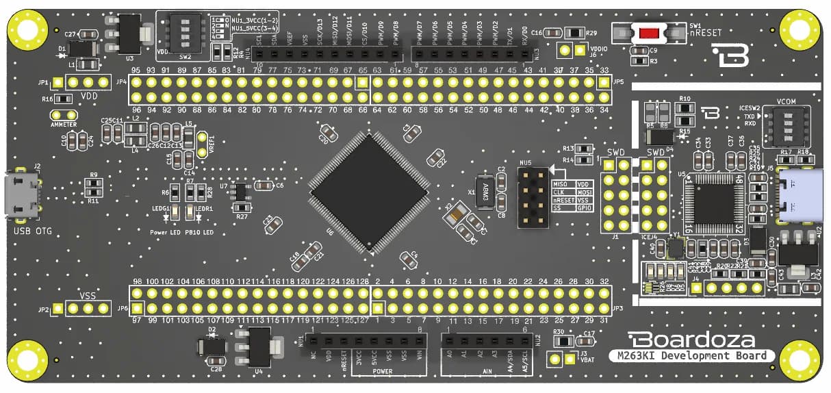
The NuMaker-M263KI consists of two parts, a M263 platform and an on-board Nu-Link2-Me debugger and programmer. The NuMaker-M263KI allows users to quickly develop and easily program and debug application.
The NuMaker-M263 offers M263KI full pins extension connectors, Arduino UNO compatible extension connectors and diversified power supply option. It is an easy-to-develop platform for user to expand the functionality and build the applications. The NuMaker-M263KI also provides an ammeter connector, allows user to monitor the microcontroller’s power consumption during development.
The Nu-Link2-Me is a debugger and programmer that supports on-line programming and debugging through SWD interface. Nu-Link2-Me provides virtual COM port (VCOM) function to print out messages on PC. Nu-Link2-Me can be separated from NuMaker-M263KI, allowing user programming and debugging functionality for other projects.
Key Features
- M263KIAAE full pins extension connectors
- Arduino UNO compatible extension connectors
- Ammeter connector for measuring the microcontroller’s power consumption
- External VDD power connector
- Arduino UNO compatible extension connector Vin
- USB power connector on M263 platform
- ICE USB connector on Nu-Link2-Me
- Debug through SWD interface
- On-line programming
- Virtual COM port function
Technical Specifications
- Item
- Boardoza NuMakerM263KI
- Input Voltage
- ( Look at the table below )
- Board Dimensions
- 63x137.5mm
- Mounting Hole Size
- 4 x M3
- Configuration 1
- Target Chip Voltage: 3.3 V; Vin \[1\]: 7 V \~ 12 V Input; J2: X; NuLink USB (J5): Ignore; SW2 Selection: NU1_3VCC; JP1: 3.3 V output
- Configuration 2
- Target Chip Voltage: 3.3 V; Vin \[1\]: X; J2: Connect to PC; NuLink USB (J5): Ignore; SW2 Selection: NU1_3VCC; JP1: 3.3 V output
- Configuration 3
- Target Chip Voltage: 5 V (Short the pads of R12 and R4 ); Vin \[1\]: 7 V \~ 12 V Input; J2: X; NuLink USB (J5): Ignore; SW2 Selection: NU1_5VCC; JP1: 5V output
- Configuration 4
- Target Chip Voltage: 5 V (Short the pads of R12 and R4 ); Vin \[1\]: X; J2: Connect to PC; NuLink USB (J5): Ignore; SW2 Selection: NU1_5VCC; JP1: 5V output
- Configuration 5
- Target Chip Voltage: 3.3 V; Vin \[1\]: Ignore \[5\]; J2: Ignore \[5\]; NuLink USB (J5): Connect to PC; SW2 Selection: OFF; JP1: 3.3 V output
Support
For technical questions, documentation and issue reports, use the GitHub repository or write to us directly.