
Boardoza FT800 TFT Driver Breakout Board
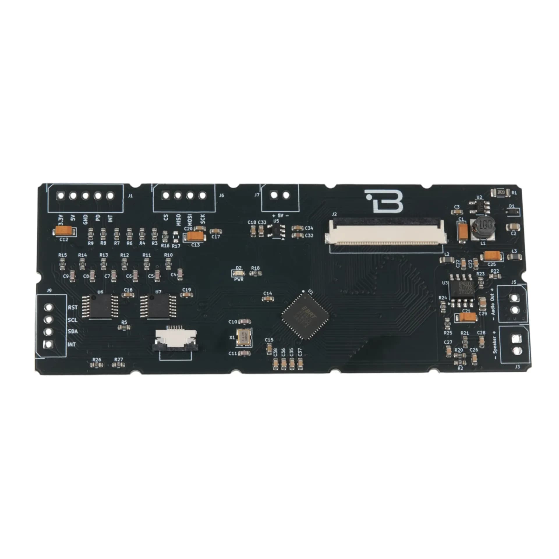
The Boardoza FT800 TFT Driver Breakout Board is a powerful graphics controller solution designed to simplify the creation of high-quality Human-Machine Interfaces (HMIs) for makers and embedded developers. Powered by the Bridgetek (FTDI) FT800 Embedded Video Engine (EVE), this module unburdens your main microcontroller by handling complex graphics rendering, audio processing, and touch control on a dedicated chip. It is the perfect bridge for connecting low-cost MCUs to sophisticated color displays. Operating with a 5V supply, the board communicates via a standard SPI interface at speeds up to 30 MHz, making it compatible with popular platforms including Arduino, ESP32, STM32, and Raspberry Pi. It supports WQVGA (480x272) and QVGA (320x240) resolution TFT displays through a standard 40-pin FPC connector. Beyond graphics, it includes a built-in audio engine with PWM output for direct speaker connection. The FT800 offers flexible touch input options with integrated resistive touch support and native capacitive touch connectivity via I²C, providing a complete multimedia solution for industrial control panels, medical devices, IoT projects, and smart home interfaces.
Where to buy?


Key Features
- Dual Resolution Support: Compatible with WQVGA (480x272) and QVGA (320x240) TFT panels with both DE mode and VSYNC/HSYNC synchronization.
- Works with any MCU: Uses standard SPI, compatible with Arduino, ESP32, STM32, Raspberry Pi Pico, and more.
- Resistive & Capacitive Touch Support: Integrated resistive and capacitive touch controller support via I²C.
- Audio Output: Mono audio channel with PWM output and dedicated speaker connections.
- Object-Oriented Architecture: Advanced command-based system enables low-cost host MCUs to create sophisticated HMI applications.
- Perfect for custom HMIs: Great for dashboards, robotics screens, measurement devices, smart panels, and DIY UI projects.
- Display Control Signals: Built-in display enable, pixel clock, and sync signal outputs for direct TFT panel control.
- Interrupt Capability: Hardware interrupt output for efficient event-driven programming.
Technical Specifications
- Model
- FT800
- Manufacturer
- Bridgetek (FTDI)
- Input Voltage
- 5V
- Type
- 40-Pin FPC
- Current
- 150mA
- Functions
- Embedded Video Engine (Graphics Controller, Audio Processor, Touch Controller)
- Interface
- SPI (up to 30 MHz), I²C (capacitive touch)
- Resolutions
- WQVGA (480x272), QVGA (320x240)
- Display Modes
- Data Enable (DE), VSYNC/HSYNC
- Touch Input
- Resistive (integrated), Capacitive (external via I²C) Color
- Color Depth
- RGB666 (18-bit, 6-bit per color channel)
- Audio Output
- Mono PWM audio channel
- Operating Temperature
- -40°C ~ +85°C
- Board Dimensions
- 40mm x 100mm
Board Pinout
( J1 ) Power and Control
| Pin Number | Pin Name | Description |
|---|---|---|
| 1 | 3V3 | 3.3V Voltage Output |
| 2 | 5V | Board Supply Input |
| 3 | GND | Ground |
| 4 | PD | Power Down / Board Enable (Active High, 3.3V-5V compatible) |
| 5 | INT | Interrupt Output (3.3V logic level) |
( J2 ) TFT Display & Touch Interface
| Pin Number | Pin Name | Description |
|---|---|---|
| 1 | LED- | LED Backlight Driver Negative |
| 2 | LED+ | LED Backlight Driver Positive |
| 3 | GND | Ground |
| 4 | VDD | 3.3V Power Output |
| 5 | GND | Ground |
| 6 | GND | Ground |
| 7 | R2 | Red RGB Signal Bit 2 |
| 8 | R3 | Red RGB Signal Bit 3 |
| 9 | R4 | Red RGB Signal Bit 4 |
| 10 | R5 | Red RGB Signal Bit 5 |
| 11 | R6 | Red RGB Signal Bit 6 |
| 12 | R7 | Red RGB Signal Bit 7 |
| 13 | GND | Ground |
| 14 | GND | Ground |
| 15 | G2 | Green RGB Signal Bit 2 |
| 16 | G3 | Green RGB Signal Bit 3 |
| 17 | G4 | Green RGB Signal Bit 4 |
| 18 | G5 | Green RGB Signal Bit 5 |
| 19 | G6 | Green RGB Signal Bit 6 |
| 20 | G7 | Green RGB Signal Bit 7 |
| 21 | GND | Ground |
| 22 | GND | Ground |
| 23 | B2 | Blue RGB Signal Bit 2 |
| 24 | B3 | Blue RGB Signal Bit 3 |
| 25 | B4 | Blue RGB Signal Bit 4 |
| 26 | B5 | Blue RGB Signal Bit 5 |
| 27 | B6 | Blue RGB Signal Bit 6 |
| 28 | B7 | Blue RGB Signal Bit 7 |
| 29 | GND | Ground |
| 30 | DATA_CLOCK | TFT Pixel Clock Output (Push-Pull) |
| 31 | DISP | Display Enable Output (Push-Pull) |
| 32 | HSYNC | Horizontal Sync Output (Push-Pull) |
| 33 | VSYNC | Vertical Sync Output (Push-Pull) |
| 34 | DE | Data Enable Output (Push-Pull) |
| 35 | NC | Not Connected |
| 36 | GND | Ground |
| 37 | X+ | Touch Screen Right Electrode |
| 38 | Y- | Touch Screen Bottom Electrode |
| 39 | X- | Touch Screen Left Electrode |
| 40 | Y+ | Touch Screen Top Electrode |
( J3 ) Speaker Output
| Pin Number | Pin Name | Description |
|---|---|---|
| 1 | Speaker+ | Speaker Output Positive |
| 2 | Speaker- | Speaker Output Negative |
( J5 ) Audio Line Output
| Pin Number | Pin Name | Description |
|---|---|---|
| 1 | Audio Out+ | Audio Line Output Positive |
| 2 | Audio Out- | Audio Line Output Negative |
( J6 ) SPI Communication
| Pin Number | Pin Name | Description |
|---|---|---|
| 1 | CS | SPI Chip Select (Active Low) |
| 2 | MISO | SPI Master In, Slave Out |
| 3 | MOSI | SPI Master Out, Slave In |
| 4 | SCK | SPI Clock Input |
( J7 ) Auxiliary Power
| Pin Number | Pin Name | Description |
|---|---|---|
| 1 | 5V+ | Board Supply Input |
| 2 | 5V- | Ground |
( J9 ) Capacitive Touch I²C Interface
| Pin Number | Pin Name | Description |
|---|---|---|
| 1 | INT | Capacitive Touch Interrupt (Active Low) |
| 2 | SDA | I²C Serial Data Pin |
| 3 | SCL | I²C Serial Clock Pin |
| 4 | RST | Capacitive Touch Reset (Active Low) |
Datasheet
Download (PDF)Support
For technical questions, documentation and issue reports, use the GitHub repository or write to us directly.