
Boardoza BNO055 Absolute Orientation Sensor Breakout Board
The Boardoza BNO055 Breakout Board is an advanced 9-axis absolute orientation sensor that combines a triaxial 14-bit accelerometer, a triaxial 16-bit gyroscope with a range of ±2000 degrees per second, and a triaxial geomagnetic sensor. This integration provides accurate and reliable orientation data for applications such as robotics, augmented reality, gaming, and personal navigation. This module operates with 3.3V or 5V, ensuring compatibility with a wide range of microcontrollers. By default, it communicates via I2C, but can be configured to UART mode using the PS0 and PS1 pins. The PS0, PS1, INT, and ADR pins operate at 3.3V, facilitating seamless interfacing with low-power MCUs.
Where to buy?


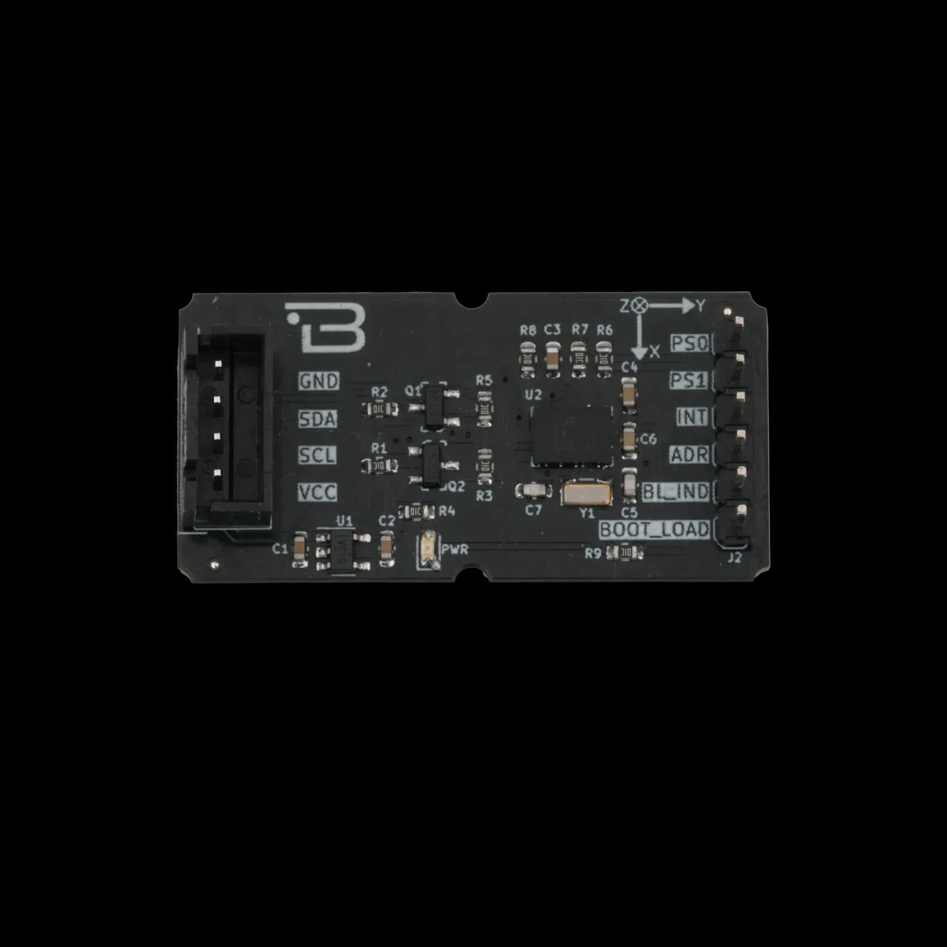
Key Features
- Integrated 9-Axis Sensor: Combines accelerometer, gyroscope, and magnetometer for comprehensive motion sensing.
- Sensor Fusion Algorithms: Built-in 32-bit microcontroller running Bosch Sensortec sensor fusion software for accurate orientation data.
- Flexible Communication Interfaces: Supports both I2C (default) and UART, selectable via PS0 and PS1 pins.
- Wide Voltage Range: Operates with 3.3V or 5V, suitable for various MCUs.
- Compact Design: Small form factor (20mm x 40mm) for easy integration into space-constrained projects.
Technical Specifications
- Model
- Bosch BNO055
- Input Voltage
- 3.3V - 5.5V
- Input Voltage
- 4-pin 2.50mm header
- Interface
- I2C (default), UART (configurable)
- Functions
- 9-Axis IMU sensor (3-axis accelerometer, 3-axis gyroscope, 3-axis magnetometer, temperature sensor) Gyroscope
- Range
- ±1300μT (X/Y-axis), ±2500μT (Z-axis)
- Resolution
- 14-bit
- Operating Temperature
- -40°C ~ +85°C
- Board Dimensions
- 20mm x 40mm
Board Pinout
( J1 ) I2C Communication Pins
| Pin Number | Pin Name | Description |
|---|---|---|
| 1 | VCC | Power Supply (3.3V - 5.5V) |
| 2 | SCL | I2C Serial Clock Pin |
| 3 | SDA | I2C Serial Data Pin |
| 4 | GND | Ground |
( J2 ) Additional Function Pins
| Pin Number | Pin Name | Description |
|---|---|---|
| 1 | BOOT_LOAD (I) | Bootloader mode select pin (active low) |
| 2 | BL_IND (O) | Bootloader indicator pin |
| 3 | ADR (I) | I2C address select pin |
| 4 | INT (O) | Interrupt output pin |
| 5 | PS1 (I) | Protocol select pin 1 |
| 6 | PS0 (I) | Protocol select pin 0 |
Datasheet
Download (PDF)Support
For technical questions, documentation and issue reports, use the GitHub repository or write to us directly.