
Regulators
Boardoza TPS630702 Buck-Boost Converter Breakout
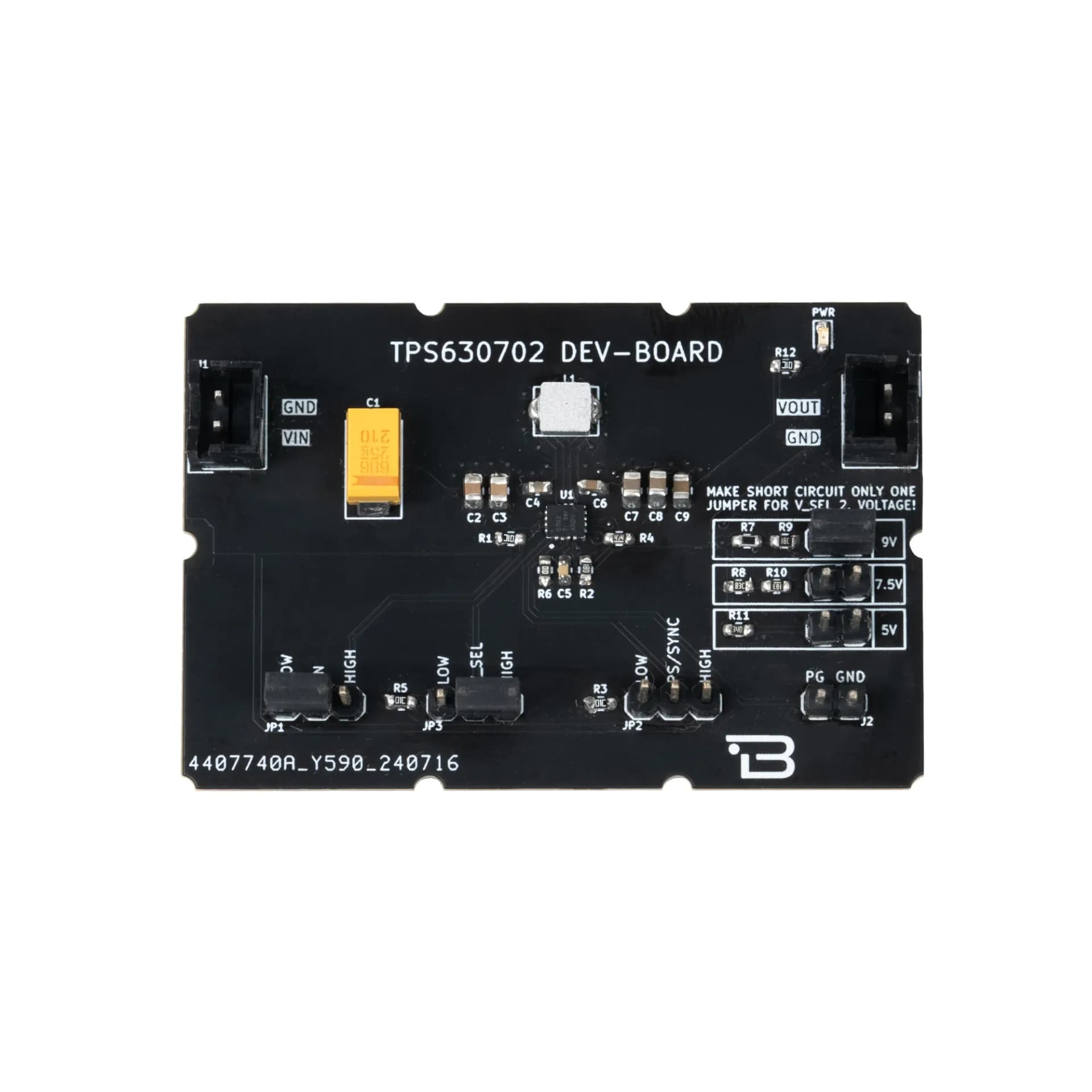
The TPS630702 Buck-Boost Converter Breakout Board is an efficient, compact power management solution for applications requiring stable voltage output over a wide input voltage range. This module features automatic transition between step-down and boost mode, making it ideal for battery-powered projects. With high efficiency of up to 95%, adjustable output voltage selection, and multiple safety protections, it provides a reliable power supply for embedded systems, IoT devices, and other electronics requiring regulated power.
Where to buy?


1 / 3
Key Features
- Wide Input Voltage Range: Operates from 2.0V to 16V, suitable for battery and adapter applications.
- Selectable Output Voltage: Provides 3.3V by default, with options for 5V, 7.5V, and 9V via jumper selection.
- High Current Capability: Supports up to 2A output in both Buck and Boost modes.
- Automatic Buck-Boost Transition: Seamlessly switches between step-down and boost mode depending on input voltage.
- Load Disconnect & Output Discharge: Ensures safety during shutdown.
- Efficiency: Up to 95%, reducing heat dissipation and improving battery life.
- Protection Features: Includes input/output overvoltage protection and undervoltage lockout.
Technical Specifications
- Voltage
- 2.0V - 16V
- Type
- Molex 2-pin 2.50mm header
- Functions
- Buck-Boost Voltage Regulator
- Output Voltage
- 3.3V, 5V, 7.5V, 9V (Selectable)
- Output Current
- Buck Mode: 2A Boost Mode: 2A (VIN = 4V, VOUT = 5V)
- Efficiency
- Up to 95%
- Operating Temperature
- -40°C ~ +150°C
- Board Dimensions
- 40mm x 60mm
Board Pinout
J1 - Power Input Connector
| Pin Number | Pin Name | Description |
|---|---|---|
| 1 | VIN | Voltage Input Pin (2V - 16V) |
| 2 | GND | Ground |
J2 - Power Good (PG) Indicator
| Pin Number | Pin Name | Description |
|---|---|---|
| 1 | PG | Power Good signal, indicating output voltage status. |
| 2 | GND | Ground |
J3 - Output Connector
| Pin Number | Pin Name | Description |
|---|---|---|
| 1 | VOUT | Adjustable Buck-Boost output (3.3V - 5V - 7.5V - 9V) |
| 2 | GND | Ground |
JP1 - Enable Control
| Pin Number | Pin Name | Description |
|---|---|---|
| 1 | LOW | Connect to GND |
| 2 | EN | Regulator Enable Pin (Default: HIGH). Set LOW to disable the regulator. |
| 3 | HIGH | Connect to VIN |
JP2 - Power Save / Synchronization Mode
| Pin Number | Pin Name | Description |
|---|---|---|
| 1 | LOW | Open drain power good output |
| 2 | PS/SYNC | Selects between forced PWM and power-save mode. Default: LOW (PWM Mode). |
| 3 | HIGH | Connect to VIN |
JP3 - Voltage Selection
| Pin Number | Pin Name | Description |
|---|---|---|
| 1 | LOW | Open drain power good output |
| 2 | V_SEL | Voltage selection input (Default: LOW for 3.3V). Set HIGH to select another voltage. |
| 3 | HIGH | Connect to VIN |
Datasheet
Download (PDF)Support
For technical questions, documentation and issue reports, use the GitHub repository or write to us directly.