
Boardoza RFM6601W LoRa Wireless Breakout Board
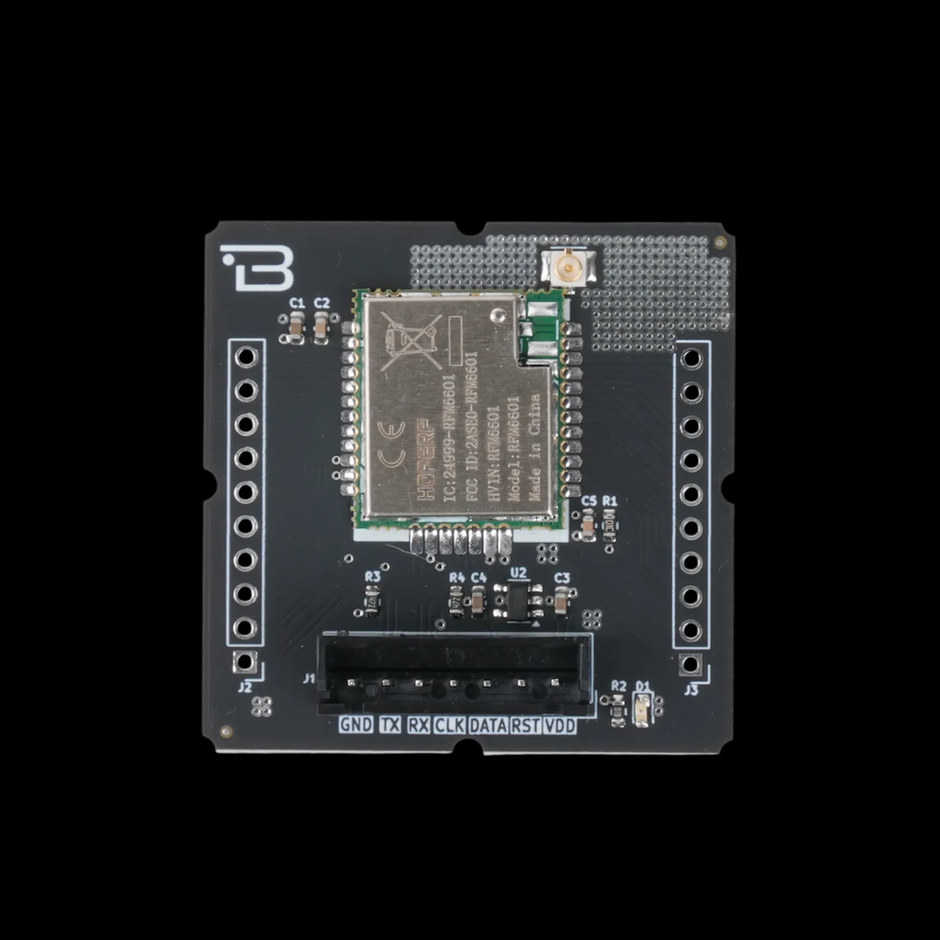
The Boardoza RFM6601W is a LoRa wireless communication module designed by HOPERF, featuring an integrated LoRa transceiver, RF transmitter/receiver, and a powerful 32-bit ARM Cortex-M4 RISC microcontroller operating at 48 MHz. This module is ideal for long-range, low-power wireless applications including IoT sensor networks, smart agriculture, industrial monitoring, and remote telemetry systems. The module operates with 3.3V or 5V supply voltage and communicates via UART interface, making it compatible with a wide range of microcontroller platforms. It supports operating frequencies 868 MHz with exceptional receiving sensitivity of -138 dBm at maximum spreading factor.
Where to buy?


Key Features
- Integrated MCU: 32-bit ARM Cortex-M4 processor at 48 MHz.
- Operation Frequency Range: 868 MHz ISM bands.
- High Sensitivity: –138 dBm at SF=12, BW=125 kHz.
- Adjustable Output Power: Up to +2 dBm.
- Low Power Consumption: 10 mA RX, 20 mA TX at +2 dBm.
- Simple UART Interface: Easy integration with most microcontrollers.
- Dual Voltage Support: Operates at 3.3V or 5V.
- Compact Form Factor: Ideal for wireless embedded applications.
Technical Specifications
- Manufacturer
- HOPERF
- Model
- RFM6601W
- Voltage
- 3.3V - 5V Voltage Input
- Type
- 7-pin 2.50mm header
- Interface
- UART
- Functions
- LoRa Wireless Communication Module
- Processor
- ARM Cortex-M4 32-bit RISC MCU
- Speed
- 48 MHz
- Range
- 868 MHz - 868.2 MHz (continuous coverage)
- Frequencies
- 868 MHz
- Sensitivity
- -138 dBm @SF=12, BW=125KHz
- Current
- 10 mA @868.1MHz
- Temperature
- -40°C ~ +85°C
- Dimensions
- 40mm x 40mm
Board Pinout
( J1 ) Main Communication & Power Pins
| Pin Number | Pin Name | Description |
|---|---|---|
| 1 | GND | Ground |
| 2 | TX | MCU GPIO (UART_RXD) |
| 3 | RX | MCU GPIO (UART_TXD) |
| 4 | CLOCK | SWD CLK (Serial Wire Debug Clock) |
| 5 | DATA | SWD DATA (Serial Wire Debug Data) |
| 6 | RESET | Reset signal (active low) |
| 7 | VDD | Power supply input (3.3V - 5V) |
( J2 ) GPIO Extension Pins
| Pin Number | Pin Name | Description |
|---|---|---|
| 1 | GPIO32 | MCU General Purpose I/O |
| 2 | GPIO33 | MCU General Purpose I/O |
| 3 | GPIO37 | MCU General Purpose I/O |
| 4 | GPIO1 | MCU General Purpose I/O |
| 5 | GPIO0 | MCU General Purpose I/O |
| 6 | GPIO03 | MCU General Purpose I/O |
| 7 | GPIO02 | MCU General Purpose I/O |
| 8 | GPIO16 | MCU General Purpose I/O |
| 9 | GPIO14 | MCU General Purpose I/O |
| 10 | GPIO15 | MCU General Purpose I/O |
( J3 ) GPIO Extension Pins
| Pin Number | Pin Name | Description |
|---|---|---|
| 1 | GPIO44 | MCU General Purpose I/O |
| 2 | GPIO45 | MCU General Purpose I/O |
| 3 | GPIO47 | MCU General Purpose I/O |
| 4 | GPIO09 | MCU General Purpose I/O |
| 5 | GPIO04 | MCU General Purpose I/O |
| 6 | GPIO05 | MCU General Purpose I/O |
| 7 | GPIO08 | MCU General Purpose I/O |
| 8 | GPIO11 | MCU General Purpose I/O |
| 9 | GPIO58 | MCU General Purpose I/O |
| 10 | GPIO60 | MCU General Purpose I/O |
Datasheet
Download (PDF)Support
For technical questions, documentation and issue reports, use the GitHub repository or write to us directly.