
Boardoza ESP32-S3 Pulse Development Board
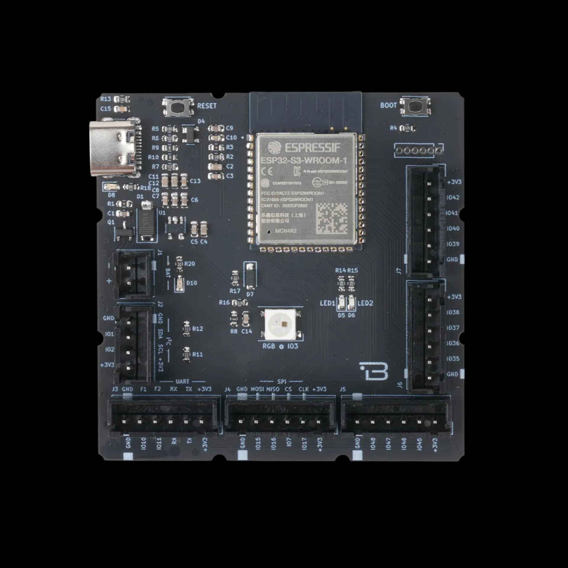
The Boardoza Pulse ESP32-S3 is a high-performance development board based on the ESP32-S3-WROOM-1-N4R2 module, designed for rapid prototyping and deployment of IoT, smart home, wearable, and industrial applications. Featuring a dual-core processor, Wi-Fi and Bluetooth 5.0 LE connectivity, and multiple I/O options, this board is optimized for both performance and versatility. It supports popular development environments like Arduino IDE, PlatformIO, and ESP-IDF, enabling developers to accelerate project timelines. A USB Type-C connector provides fast programming and power, while battery input support makes it ideal for mobile and low-power systems.
Where to buy?


Key Features
- ESP32-S3 SoC: Dual-core Xtensa® LX7 CPU with 240 MHz clock speed, integrated Wi-Fi (802.11 b/g/n) and Bluetooth 5.0 LE.
- Extensive Peripheral Support: 22 GPIOs and built-in interfaces for SPI, UART, I²C, ADC, DAC, and PWM.
- USB Type-C Interface: Simplifies programming and powering via a modern, reversible connector.
- Battery Compatibility: Supports 1S Li-Ion battery input, suitable for portable applications.
- Addressable RGB LED: Integrated RGB LED for status indication or visual feedback.
- Ultra-Low Power Modes: Deep sleep and other energy-saving modes extend battery life significantly.
- Wide IDE Support: Works with ESP-IDF, Arduino, PlatformIO, and other development ecosystems.
Technical Specifications
- Model
- ESP32-S3-WROOM-1-N4R2
- Type
- Type-C or Li-Ion Battery
- Input Voltage
- 5V (via Type-C) or 3.7V (1S Battery)
- Processor
- Dual-Core Xtensa® LX7
- Clock Speed
- Up to 240 MHz
- Wi-Fi
- 802.11 b/g/n
- Bluetooth
- Bluetooth 5.0 LE
- Flash Memory
- 8MBSRAM: 512KB
- USB Port
- USB Type-C (Power + Programming)
- Connectivity Interfaces
- SPI, I²C, UART, PWM, ADC, DAC
- GPIO Pins
- 22
- Power Modes
- Multiple low-power options
- Functions
- Development Board
- Operating Temperature
- -40°C ~ +85°C
- Board Dimensions
- 60mm x 60mm
Board Pinout
( J1 ) Battery Connector
| Pin Number | Pin Name | Description |
|---|---|---|
| 1 | BAT- | Battery Negative Input |
| 2 | BAT+ | Battery Positive Input |
( J3 ) I²C Connector
| Pin Number | Pin Name | Description |
|---|---|---|
| 1 | GND | Ground |
| 2 | IO2 | I²C Clock (SCL) |
| 3 | IO1 | I²C Data (SDA) |
| 4 | +3V3 | Voltage Output |
( J4 ) UART Connector
| Pin Number | Pin Name | Description |
|---|---|---|
| 1 | GND | Ground |
| 2 | TX (IO43) | UART Transmit |
| 3 | RX (IO44) | UART Receive |
| 4 | IO11 | Function Pin 2 |
| 5 | IO10 | Function Pin 1 |
| 6 | +3V3 | Voltage Output |
( J5 ) SPI Connector
| Pin Number | Pin Name | Description |
|---|---|---|
| 1 | GND | Ground |
| 2 | IO17 | SPI Clock (CLK) |
| 3 | IO7 | Chip Select (CS) |
| 4 | IO16 | MISO |
| 5 | IO15 | MOSI |
| 6 | +3V3 | Voltage Output |
( J6 ) GPIO Extension
| Pin Number | Pin Name | Description |
|---|---|---|
| 1 | GND | Ground |
| 2 | IO38 | General I/O |
| 3 | IO37 | General I/O |
| 4 | IO36 | General I/O |
| 5 | IO35 | General I/O |
| 6 | +3V3 | Voltage Output |
( J7 ) GPIO Extension
| Pin Number | Pin Name | Description |
|---|---|---|
| 1 | GND | Ground |
| 2 | IO42 | General I/O |
| 3 | IO41 | General I/O |
| 4 | IO40 | General I/O |
| 5 | IO39 | General I/O |
| 6 | +3V3 | Voltage Output |
( J8 ) GPIO Extension
| Pin Number | Pin Name | Description |
|---|---|---|
| 1 | GND | Ground |
| 2 | IO45 | General I/O |
| 3 | IO46 | General I/O |
| 4 | IO47 | General I/O |
| 5 | IO48 | General I/O |
| 6 | +3V3 | Voltage Output |
Datasheet
Download (PDF)Support
For technical questions, documentation and issue reports, use the GitHub repository or write to us directly.