
Boardoza E-Paper Driver 24 Pin Breakout Board
The Boardoza E-Paper Driver 24-Pin Breakout Board makes it easy to add a clear, paper-like display to microcontroller-based projects. E-paper displays are highly readable in bright environments and can retain the last displayed image even after power is removed. Because they primarily consume power only during screen updates, they are well suited for battery-powered applications such as electronic shelf labels, smart badges, price tags, information panels, industrial indicators, and low-power IoT devices. The board features a standard 24-pin FFC/FPC connector and the power circuitry required to operate compatible e-paper panels, eliminating the need for a separate driver circuit. It supports SPI- and I²C-compatible signals, provides a busy-status output to indicate when the display is refreshing, and can be used with compatible monochrome and multi-color e-paper panels, including black-white-red and black-white-red-yellow display types.
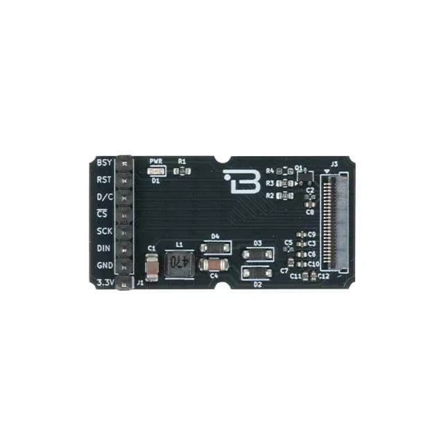
Product Details
Key Features
- Integrated DC-DC Booster: Generates the required positive and negative gate voltages for E-Paper panel driving.
- Ultra-Low Power Operation: Optimized for battery-powered and energy-efficient display systems.
- Hardware Busy Monitoring: Includes a dedicated BSY (Busy) pin for display refresh status indication.
- Flexible Communication: Supports SPI and I²C communication for simple MCU integration.
- Reliable Display Driving: Stable power sequencing improves image consistency and display contrast performance.
- Monochrome and Multi-Color Panel Support: Supports compatible 2-color, 3-color, and 4-color 24-pin E-Paper panels, including black/white, black/white/red, and black/white/red/yellow display types.
Technical Specifications
- Model
- E-Paper Display Driver
- Manufacturer
- Boardoza
- Communication Interface
- SPI / I²C-Compatible Signaling
- Input Voltage
- 3.3V
- Display Connector
- 24-Pin E-Paper Connector
- Integrated Power Circuit
- DC-DC Booster with Gate Voltage Generation
- Busy Status Output
- Available (BSY Pin)
- Operating Temperature
- -40°C to +85°C
- Board Dimensions
- 40mm x 20mm
Board Pinout
( J1 ) Communication Connector
| Pin Number | Pin Name | Description |
|---|---|---|
| 1 | 3.3V | 3.3V Power Supply Input |
| 2 | GND | Ground |
| 3 | DIN | SPI Data Input (MOSI) / SDA |
| 4 | SCK | SPI Clock Input / SCL |
| 5 | nCS | SPI Chip Select (Active Low) |
| 6 | D/C | Data / Command Selection |
| 7 | RST | Hardware Reset Input |
| 8 | BSY | Busy Status Output |
( J2 ) 24-Pin E-Paper Display Connector
| Pin Number | Pin Name | Description |
|---|---|---|
| 1 | NC | Not Connected |
| 2 | GDR | Gate Driver Control Signal |
| 3 | RESE | Current Sense / Resistor Sense Signal |
| 4 | VGL | Negative Gate Driving Voltage |
| 5 | VGH | Positive Gate Driving Voltage |
| 6 | TSCL | Touch / Auxiliary Serial Clock |
| 7 | TSDA | Touch / Auxiliary Serial Data |
| 8 | BS | Interface Selection Signal |
| 9 | BUSY | Busy Status Output |
| 10 | RES | Hardware Reset Input |
| 11 | D/C | Data / Command Selection |
| 12 | CS | SPI Chip Select |
| 13 | SCLK | SPI Clock Input |
| 14 | SDI | SPI Data Input |
| 15 | VDDIO | I/O Logic Power Supply |
| 16 | VCI | Power Supply Input |
| 17 | VSS | Ground |
| 18 | VDD | Logic Power Supply |
| 19 | VPP | Programming / Panel Power Voltage |
| 20 | VSH1 | Positive Source Driving Voltage |
| 21 | PVGH | Positive Gate Pump Voltage |
| 22 | VSL | Negative Source Driving Voltage |
| 23 | PVGL | Negative Gate Pump Voltage |
| 24 | VCOM | Common Electrode Voltage |
Datasheet
Download (PDF)Support
For technical questions, documentation and issue reports, use the GitHub repository or write to us directly.