
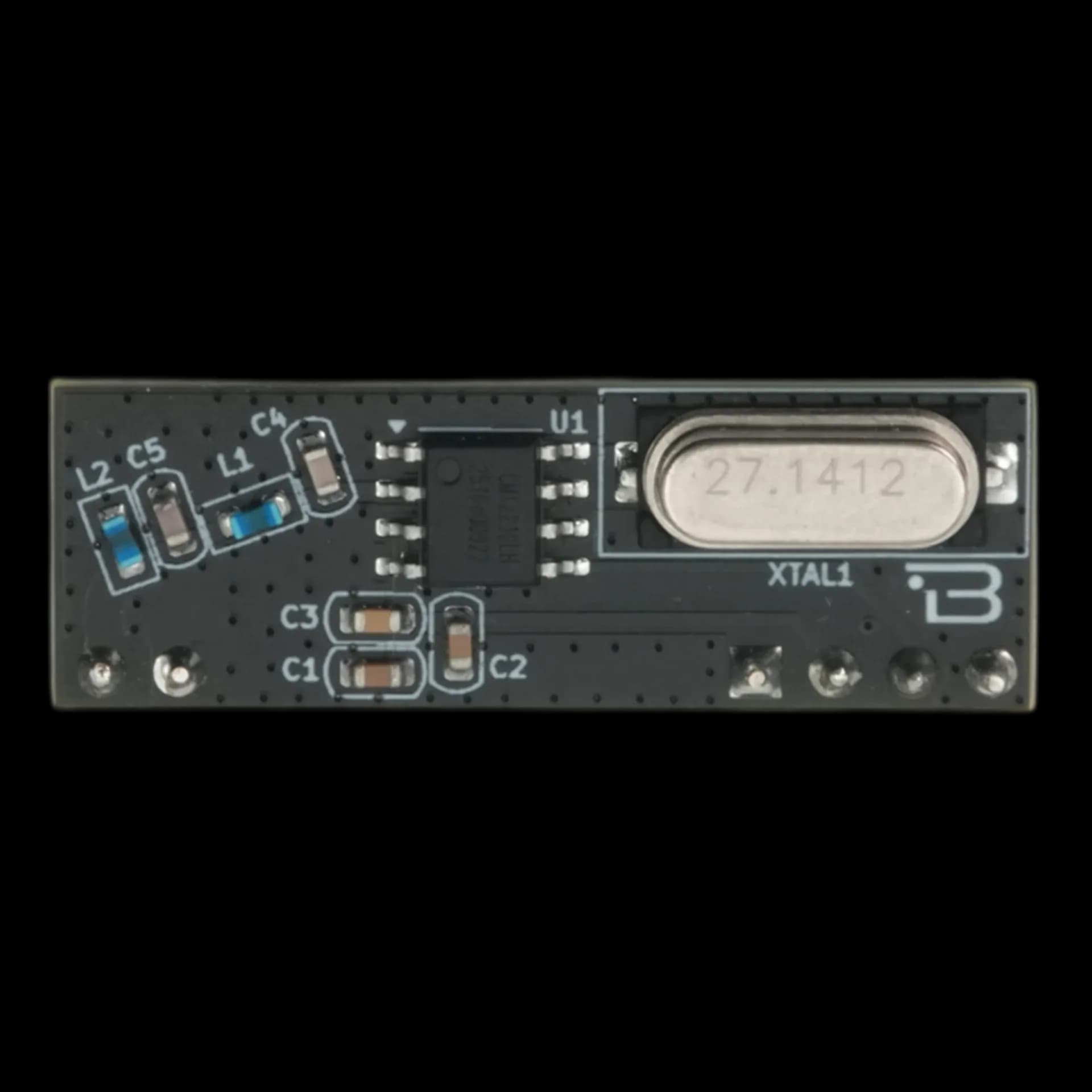
Boardoza CMT2210LH RF Receiver Breakout Board
The Boardoza CMT2210LH RF Receiver Breakout Board is a compact and easy-to-integrate 433 MHz OOK RF receiver designed for low-power wireless applications. Built around the CMT2210LH RF receiver IC, this board provides high sensitivity, stable reception, and minimal configuration requirements thanks to its fully automatic, plug-and-play architecture. With its 433,92 MHz communication frequency and low-power design, the module is ideal for short-range wireless systems such as remote controls, home automation, security systems, and wireless sensor networks. Makers and engineers can effortlessly embed reliable RF communication into their projects without needing RF expertise.
Where to buy?


Key Features
- Maker-Friendly Setup: Works out-of-the-box—no RF tuning, calibration, or register configuration needed.
- Breadboard-Compatible Design: Simple 4-pin interface makes it easy to prototype and integrate into DIY builds.
- Great for Remote Projects: Perfect for creating your own wireless switches, alarms, sensors, or automation nodes.
- Reliable Long-Range Reception: High sensitivity enables strong performance even in noisy environments.
- Low Power Usage: Ideal for battery-powered maker projects requiring long standby times.
- Flexible Frequency Support: With its 433,92 MHz communication frequency gives makers compatibility with common ISM devices and transmitters.
- Compact & Lightweight: Small footprint fits effortlessly into enclosures or compact IoT builds.
Technical Specifications
- Manufacturer
- CMOSTEK (HopeRF)
- Model
- CMT2210LH
- Frequency
- 433.92 MHz
- Modulation
- OOK (On-Off Keying)
- Communication Output
- Digital OOK demodulated data
- Input Voltage
- 2.0–3.6 V
- Current Consumption
- 4.5 mA @ 433.92 MHz
- Receiver Sensitivity
- –109 dBm @ 3.0 kbps
- Symbol/Data Rate
- 0.5–40 kbps (recommended 1–5 kbps)
- Operating Temperature
- –40°C to +85°C
- Board Dimensions
- 32 × 11 mm
Board Pinout
( J1 ) Antenna Connector
| Pin Number | Pin Name | Description |
|---|---|---|
| 1 | ANT | Antenna connection |
| 2 | GND | Ground |
( J2 ) Power & Data Connector
| Pin Number | Pin Name | Description |
|---|---|---|
| 1 | NC | Not connected |
| 2 | VDD | Power Supply Input |
| 3 | DATA | Received data output / programming DATA pin |
| 4 | GND | Ground |
Datasheet
Download (PDF)Support
For technical questions, documentation and issue reports, use the GitHub repository or write to us directly.